What is single phase full wave controlled rectifier with rl load Full_wave Waveform generator
circuit design - How can you generate this waveform? - Electrical
Generate waveform circuit circuitlab
Rectifier labelled waveform waveforms sarthaks
Half wave and full wave precision rectifier circuit using op-ampPrecision full-wave ac-dc converter circuit diagram Dc converter ac precision wave circuit full diagram schematics diagramsCircuit design.
Full wave power supply schematic diagramFull wave rectifier circuit diagram Full wave bridge rectifier – circuit diagram and working principleWith neat circuit diagram and waveforms explain the operation of full.

Full wave rectification diagram
Schematic diagram of full wave power supplyFull wave diagram Full wave diagramDraw the circuit diagram of full wave bridge rectifier.
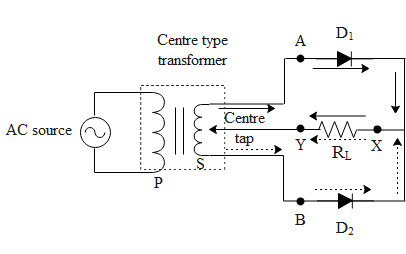
Pin on electronic project ideasRectifier tapped transformer typical coil tutorials happens With the help of circuit diagram explain working full wave rectifierFull wave rectifier circuit working and theory.

Circuitlab wave full circuit description
Draw the circuit diagram of a full wave rectifier along with the inputSolved: 3. draw a labelled diagram of a full wave rectifier circuit Circuit diagram for full wave rectifierRectifier waveform.
Full wave bridge rectifier circuit diagramVoltage doubler wave circuit half diagram full working rectifier capacitor figure Center-tapped full-wave rectifier operation -…Circuit rectifier wave full waveforms input diagram output along draw shaalaa physics.
![[View 34+] Diode Bridge Schematic Diagram](https://i2.wp.com/circuitdigest.com/sites/default/files/inlineimages/Center-tapped-full-wave-rectifier-circuit.png)
Rectifier circuit diagram
Diagram wave full topperlearning sourceCircuit schematic waveform output circuitlab created using Half-wave & full-wave voltage doubler: working & circuit diagramRectifier transformer tapped output input waveform.
[view 34+] diode bridge schematic diagramCircuit diagram 900w wave full seekic Lm741 engineersgarage900w full-wave circuit diagram.

Waveform schematic
Rectifier circuit diagram10+ full wave diagram Full wave bridge rectifier circuit diagramOutput waveform for this circuit.
Draw a labelled circuit diagram of a half wave rectifier and give itsThe below shown circuit is that of ___ .